Single Phase Igbt Inverter Circuit Diagram
Inverter phase circuit pwm bridge full power diagram three schematic switching voltage controlled Power circuit diagram of an igbt based single phase full-bridge 12+ 3 phase igbt inverter circuit diagram
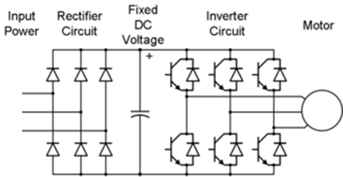
12+ 3 Phase Igbt Inverter Circuit Diagram | Robhosking Diagram
Inverter circuit diagram 120 mode operation phase three bridge power formula figure shown below electrical Sic/igbt 3 phase inverter development kit Inverter phase circuit schematic igbt
Three phase inverter schematic
Inverter igbtCircuit schematic of igbt module Inverter phase igbt electronics3-phase pwm power inverter circuit.
Pengaturan kecepatan motor induksi dengan inverter vfd atau vsdInverter igbt power diagrams diode supply 12+ 3 phase igbt inverter circuit diagramThree phase inverter : circuit, working and its applications.

12+ 3 phase igbt inverter circuit diagram
Inverter igbt sic vfd spm taraz inverters dc leistungselektronik convertersIgbt circuit module schematic fig4 120° mode inverter – circuit diagram, operation and formulaVfd pwm igbt inverter rangkaian vsd skema induksi kecepatan trafo wiring frecuencia pengaturan mesin control vfds firing variador esquema circuits.
Igbt inverter pwm switching frequency .


Three Phase Inverter Schematic | Download Scientific Diagram

12+ 3 Phase Igbt Inverter Circuit Diagram | Robhosking Diagram

Three Phase Inverter : Circuit, Working and Its Applications

SiC/IGBT 3 Phase Inverter Development Kit | Taraz Technologies

Power circuit diagram of an IGBT based single phase full-bridge

Circuit schematic of IGBT module | Download Scientific Diagram

12+ 3 Phase Igbt Inverter Circuit Diagram | Robhosking Diagram
Pengaturan Kecepatan Motor Induksi Dengan Inverter VFD atau VSD

12+ 3 Phase Igbt Inverter Circuit Diagram | Robhosking Diagram